

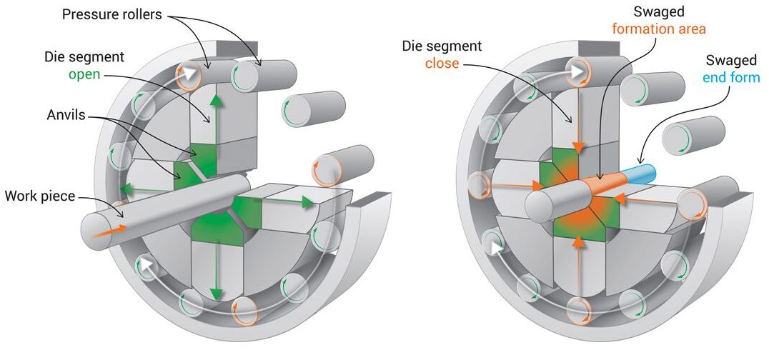
Swaging is a process that belongs to the forging class of manufacturing processes, where the dimensions of the work piece is changed using dies which apply force to the part. The process is divided into two main types; extrusion or rotary. Extrusion is similar to wire drawing, where a work piece is forced through a die to reduce the diameter. In rotary swaging, a constant hammering force is applied by a die on the work piece to reduce the diameter of the work piece.


Applications of Swaging
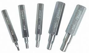
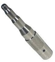
This process is used for the production of features like tapers, section steps and clamping, as well as products like closed tubes, tool shafts and exhaust pipes. Other examples that can be produced are punches, cable assemblies and chisels.

Suitable Materials
Following are the most commonly used materials that can be processed by the swaging manufacturing process:
- Aluminium and Aluminium alloys
- Nickel and its alloys
- Magnesium and its alloys
- Stainless steel
- Low carbon steel
Some less common materials that can be processed include:
- Copper and its alloys
- Lead and its alloys
- Zinc and its alloys

Design Considerations
- Contoured surfaces and splines along an axis are possible.
- Inserts and undercuts are not possible.
- Range of draft angles that can be produced is from 0 to 3.5 degrees.
- Possible section size range is from 2.5 mm to 20 mm.
- Possible diameter range is from 2.5 mm to 150 mm.
- Part length range is from 1.5 mm to 250 mm.
Process Variations
- Swage manufacturing can be done at room temperature (called cold swaging) and also at the melting or recrystallization temperature of the work piece (called hot swaging).
- Rotary swaging is always performed at room temperature and extrusion is performed at elevated temperatures.
- To generate different inside profiles, a shaped mandrel can be used.
- Hot swaging can be done manually using hand tools and an anvil. Blacksmithing is one common example of this process.
Economic Considerations
- The process can be done at a moderate production rate of up to 200-300 pieces per hour.
- Depending on the tool complexity, lead time can range from a single day to 6-7 days.
- A single tool can be used for various products of the same type.
- Swaging has excellent material utilization, with zero waste material produced.
- Automation is possible depending on production volume.
- Good suitability for low volume production.
- Labour and equipment costs are moderate, tooling cost is high.
Quality Considerations
- Swaging at room temperature gives desired mechanical properties.
- Fatigue life is improved due to compressive surface stresses.
- Surface roughness ranges from 0.8 to 3.2 micrometer Ra.
Advantages
- Can produce complex parts.
- A large range of shapes including square, round and rectangular are possible.
- Produces excellent surface finish.
- Produces excellent surface details.
Disadvantages
- Suitable only for low production processes.
- High tooling costs.
- Limited to metals only.