If you are designing a coolant plate for a battery pack, a compact cold plate for power electronics, or a hydrogen flame arrestor, you probably want predictable one way flow without adding more actuators, seals and failure modes than necessary. That need for robust, low maintenance flow control is one reason a 100 year old idea, the Tesla valve, is back in the research spotlight.
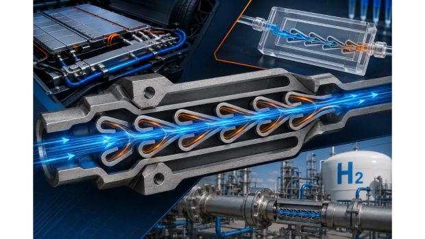
The Tesla valve is a “fluidic diode”: a static channel geometry that resists reverse flow much more than forward flow, so you get rectification without moving parts. Recent work has explored Tesla valve applications in battery cold plates, power electronics cooling, fuel cells, photovoltaic thermal systems, microfluidics and hydrogen flame arrestors, which makes it worth understanding at a practical design level.
This article focuses on how Tesla valves work, where they offer real advantages, and what you should check before you try to deploy them in EV cooling hardware, lab scale devices or hydrogen infrastructure.
Why passive flow control is back on the agenda
In many modern systems, conventional mechanical check valves are a known failure and maintenance point, particularly where there is contamination, vibration or thermal cycling. If you can get one way behaviour from geometry alone, you remove seats, springs and seals, which is attractive for long life systems in EVs, fuel cells and hydrogen piping.
At the same time, engineers are packing more function into smaller manifolds, from EV “supermanifolds” that combine multiple coolant and refrigerant paths, to compact hydrogen handling skids and meso scale combustors. In that context, a pattern like the Tesla valve, which can be replicated at different scales and integrated into plates or channels, is a natural candidate for numerical studies, laboratory prototypes and early product concepts.
What a Tesla valve actually is
Geometry and operating principle
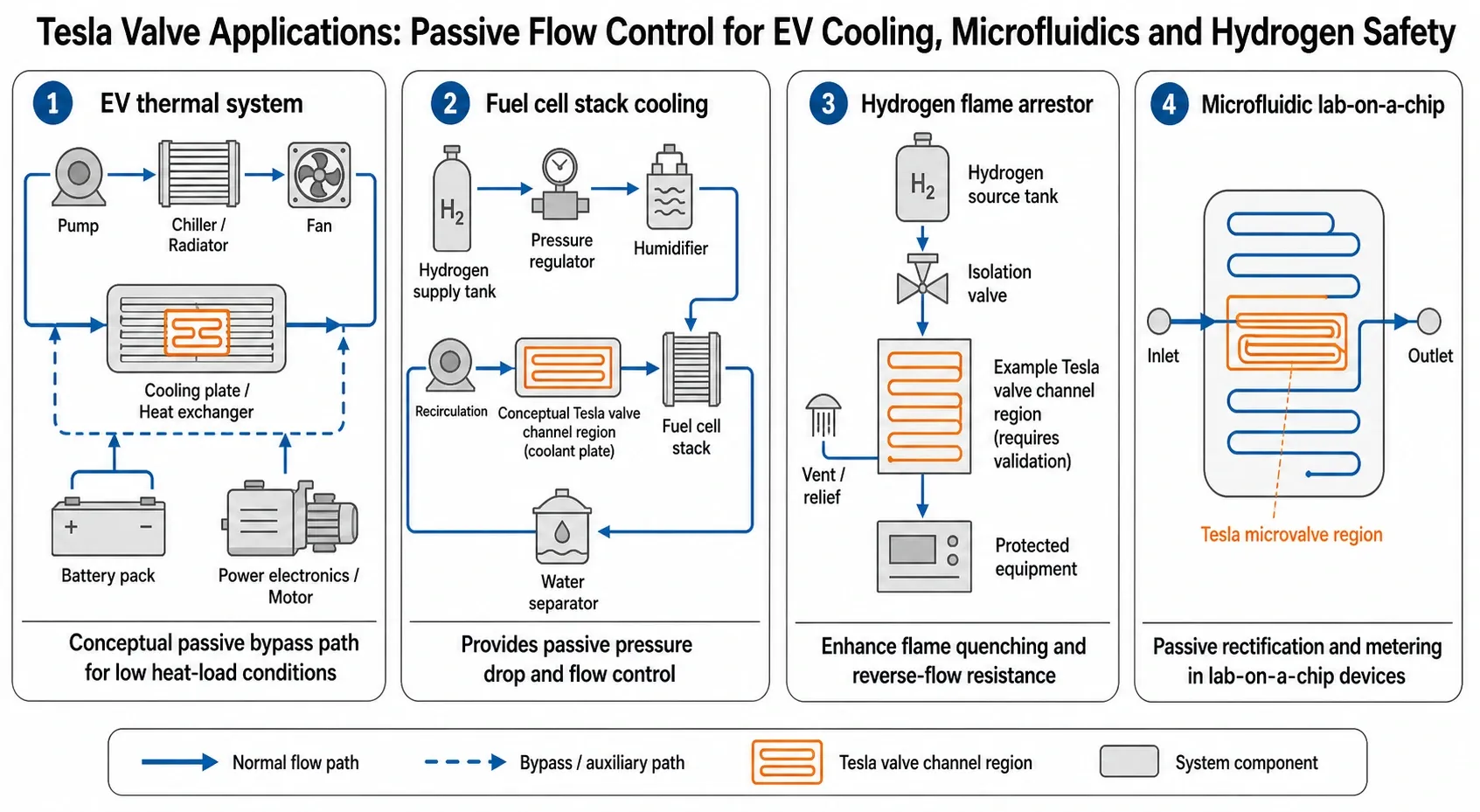
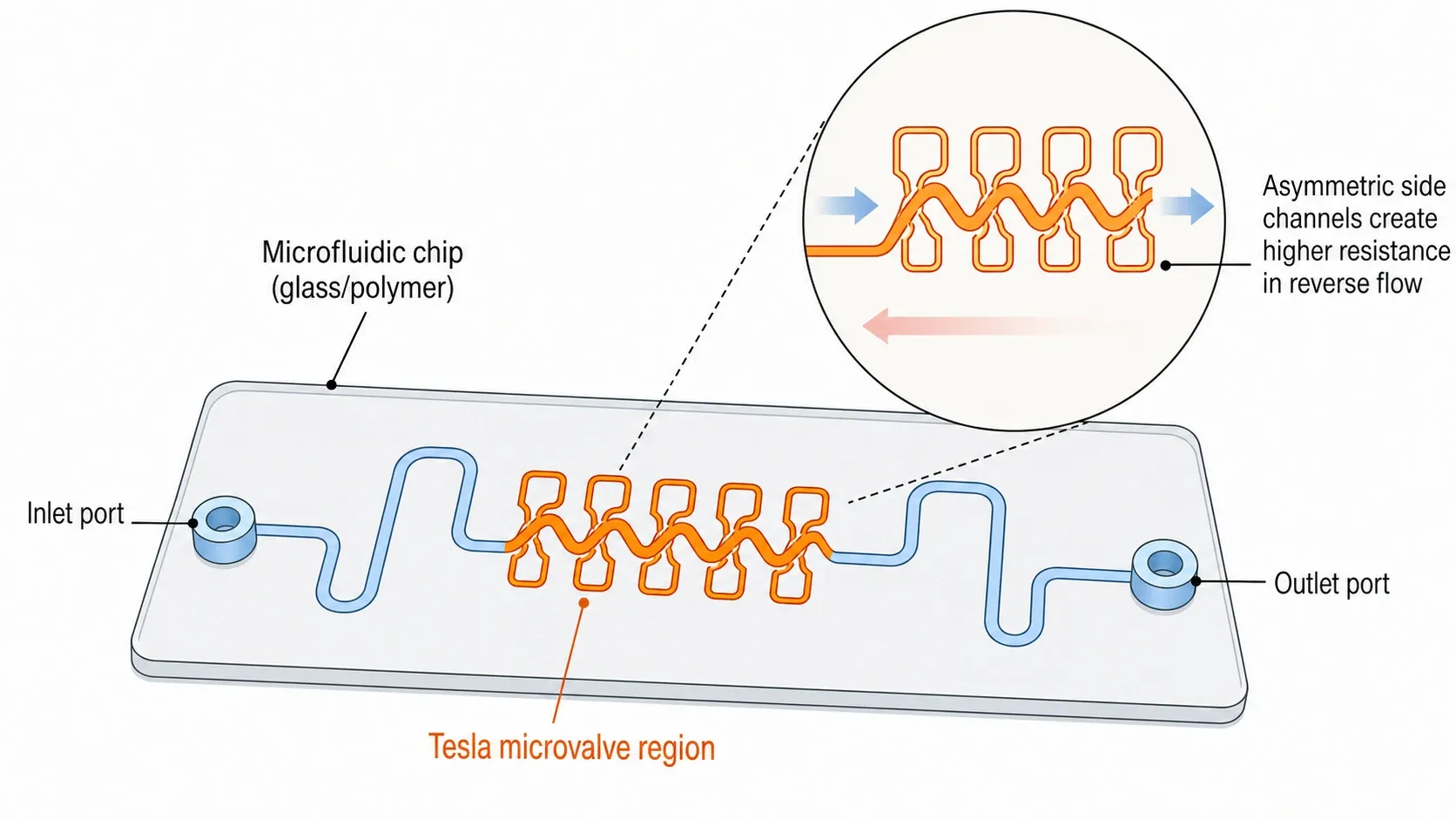
A Tesla valve is a channel network in which the main path is relatively straight in the forward direction, while a series of side channels and bends create recirculation zones and higher resistance when flow is reversed. Fluid flowing in the “easy” direction sees a smoother path with fewer sharp decelerations, whereas fluid pushed the other way is forced into sudden turns and collisions with its own recirculation structures, increasing losses.
The effectiveness is usually summarised by the diodicity, the ratio of the pressure drop in reverse flow to the pressure drop in forward flow at the same volumetric flow rate. Experimental and numerical work on micro and macro Tesla valves reports diodicity values of roughly 1.4 to above 3 depending on geometry, number of stages and Reynolds number.
Reynolds number, pulsatile flow and when the valve actually works
The Tesla valve relies on inertial effects and the formation of local vortices, so it does not perform well in very low Reynolds number flow where everything is almost creeping and linear. Macro scale studies show that diodicity can rise sharply once the Reynolds number reaches a few hundred, while microfluidic work shows useful diodicity at smaller Reynolds numbers when the geometry is carefully optimised.
Pulsatile or oscillatory flows can further enhance diodicity because vortices and recirculation structures have time to develop and interact with the incoming pulses. For engineers, that means Tesla valves are particularly interesting wherever pumps, compressors or reciprocating devices naturally create an unsteady flow that you can exploit rather than smooth out.
Tesla valves versus mechanical check valves
A conventional check valve uses a mechanical element such as a disc, ball or poppet which physically moves to block reverse flow, so in the closed direction leakage can be extremely low at moderate pressures. A Tesla valve has no such internal closure, so even at high diodicity there is always some reverse flow and its behaviour is more like a biased resistance than a hard stop.
The upside is that a Tesla valve has no moving parts to jam or wear, and it can be fabricated as part of a plate, manifold or chip with the same processes as the rest of the component. The downside is that you pay for the rectification with higher forward pressure drop and a design that is sensitive to flow regime, so it is not a straightforward replacement for a spring loaded check valve in every application.
| Aspect | Tesla valve | Check valve |
|---|---|---|
| Moving parts | None, static geometry | Poppet, spring, seat and seals |
| Reverse sealing | Finite reverse leakage, behaves as high resistance | Very low leakage in closed direction if in good condition |
| Dependence on Reynolds number | Strong, diodicity rises only in certain regimes | Function largely independent of Reynolds number in normal operation |
| Fouling and wear | No moving parts, but narrow passages can foul | Seats and moving elements can foul or stick |
| Manufacturing | Can be integrated into plates, manifolds or chips | Separate component, needs integration and sealing |
Modern Tesla valve applications in EV cooling and power electronics
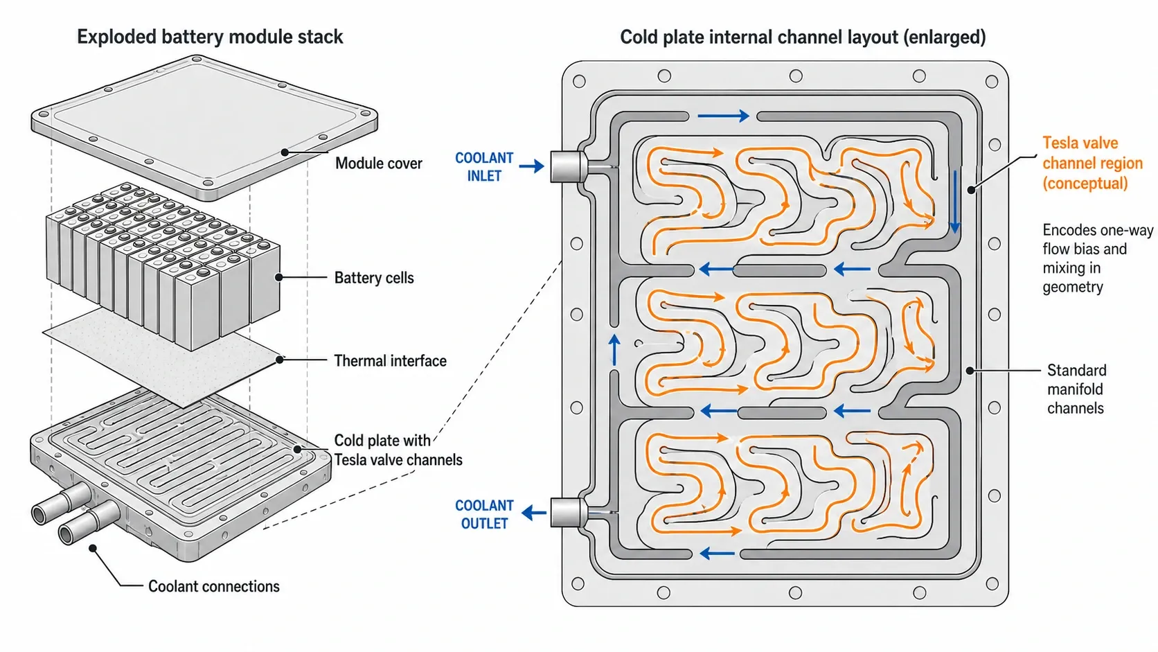
EV thermal systems have become highly integrated, with shared coolant loops serving battery packs, drive units, power electronics and often a cabin heat pump through complex manifolds and multi port valves. Public descriptions of production systems show sophisticated electromechanical valves rather than Tesla valves, while several research groups have explored Tesla valve channel patterns inside cold plates and compact cooling modules for batteries and electronics.
If you are new to the overall EV cooling problem, it is worth reading a general overview of battery and power electronics thermal management elsewhere on mechanical-engineering.com before going deeper into Tesla valve applications in this space.
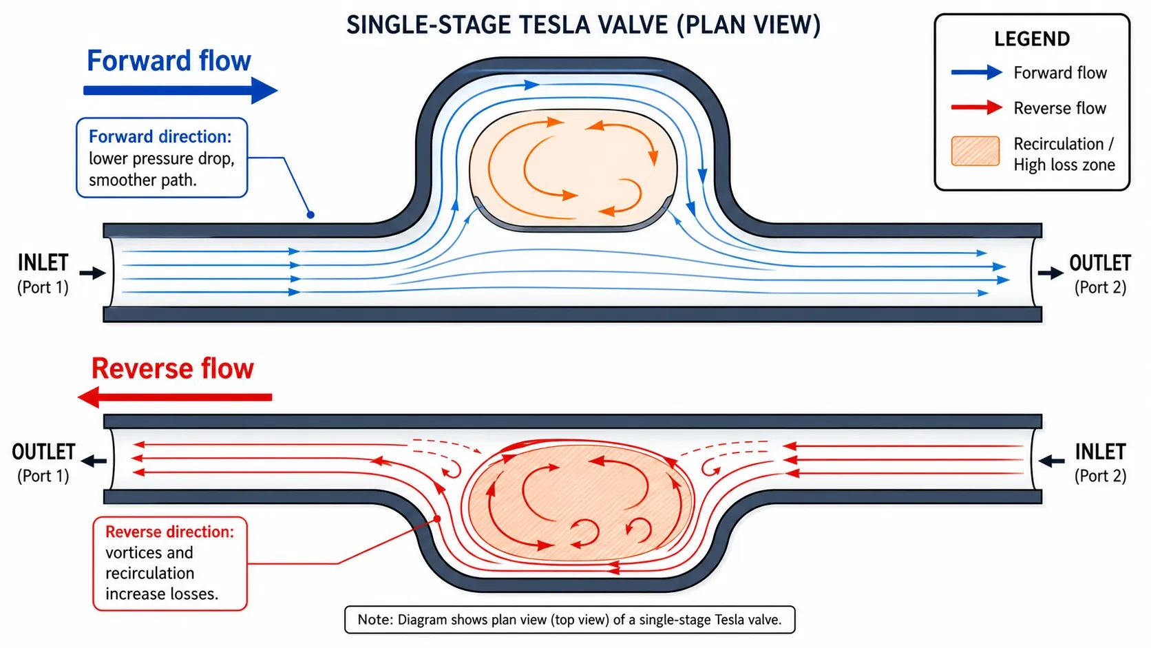
Imitation Tesla valve battery cold plates
One recent study proposed an “imitation Tesla valve liquid cooling plate” for battery modules, in which the coolant channels within the plate followed a multi stage Tesla valve pattern rather than a straight or honeycomb layout. By optimising parameters such as inlet velocity, number of channels, number of stages and staggered arrangement, the authors found a five channel, eight stage plate that controlled maximum battery temperature at about 303.02 K, limited temperature difference to 3.60 K and kept pressure drop to 42.51 Pa.
Compared with a honeycomb plate with equivalent overall size, the Tesla valve plate in that study reduced temperature difference by roughly 12 percent and cut pressure drop by about 65 percent at the design condition. These are research results for a particular plate geometry and duty cycle, not general performance guarantees, but they illustrate how Tesla style channels can be treated as candidates in cold plate optimisation rather than curiosities.
Tesla valve manifolds for power electronics cooling
Multi objective optimisation has also been used to design Tesla valve based cold plates for high heat flux SiC power devices, using channel networks that alternate forward and reverse Tesla sections to manage two phase bubbly flow. In one such numerical study, the authors reported device temperature uniformity within about plus or minus 5 degrees Celsius and maximum device temperatures around 210 degrees Celsius at heat fluxes in the order of several hundred watts per square centimetre, for a specific combination of flow rate and coolant properties.
Because the geometry can disrupt bubble slugs and enhance mixing, Tesla style channels may help avoid flow maldistribution and local dry out in high heat flux two phase cooling, at the cost of increased complexity in the channel network. If you are working on compact cold plates for inverters or DC fast charging hardware, Tesla valve patterns are worth considering in CFD driven design studies alongside more conventional pin fin and straight channel layouts.
Fuel cell and photovoltaic thermal management
Similar ideas have been applied in numerical studies of PEM fuel cell cooling, where multi stage Tesla valve channels with hybrid nanofluids improved temperature uniformity and increased heat transfer coefficients compared with straight channels. For example, one study reported that a reverse Tesla valve configuration achieved about 15 percent higher heat transfer coefficient than a straight channel, along with better temperature uniformity in the cooling plate, for a specific combination of nanofluid and operating conditions.
In photovoltaic thermal systems, simulations comparing several flow channel structures found that a Tesla valve based layout delivered higher cooling performance and allowed combined electrical and thermal efficiencies above 16 and 59 percent respectively when paired with appropriate nanofluids. Those results come from a 2024 open access study on a Tesla valve based PV/T system, which interested readers can find at this link. For engineers, these fuel cell and PV/T results mean Tesla style channels are worth including in simulation studies when you are constrained on footprint but can tolerate extra pressure drop and manufacturing complexity.
Micro and meso scale Tesla valves in chips and combustors
Microfluidic chips and lab on a chip
Tesla valves have been widely explored in microfluidics, where they can be integrated into chips as passive elements for flow rectification, metering and mixing without external actuators. A good overview of this work is the open access review “Tesla valve microfluidics: the rise of forgotten technology” and the paper “Highly efficient passive Tesla valves for microfluidic applications”, both available via this microfluidic Tesla valve article.
At low Reynolds numbers typical of many microfluidic systems, researchers have focused on optimising geometry, including angles, side channel lengths and number of stages, to get useful diodicity while keeping pressure losses within practical limits. Experimental micro Tesla valves designed with such optimisation methods have achieved diodicity of roughly 1.5 to around 2 in steady micro flows for particular designs.
Meso scale combustors and compact burners
At the meso scale, Tesla valve structures have been explored in combustors and thermophotovoltaic systems where controlling flame location and mixing is critical in a very small volume. Studies on Tesla valve structured meso scale combustors fuelled with hydrogen rich mixtures have evaluated how the channel pattern influences temperature distribution, combustion stability and overall efficiency.
These applications are still research focused, but they illustrate how the same basic Tesla valve pattern can appear from microfluidic chips up to combustors, each time exploiting the ability of the geometry to encourage or discourage flow and mixing in particular directions.
Tesla valve structures for hydrogen safety and flame arrestors
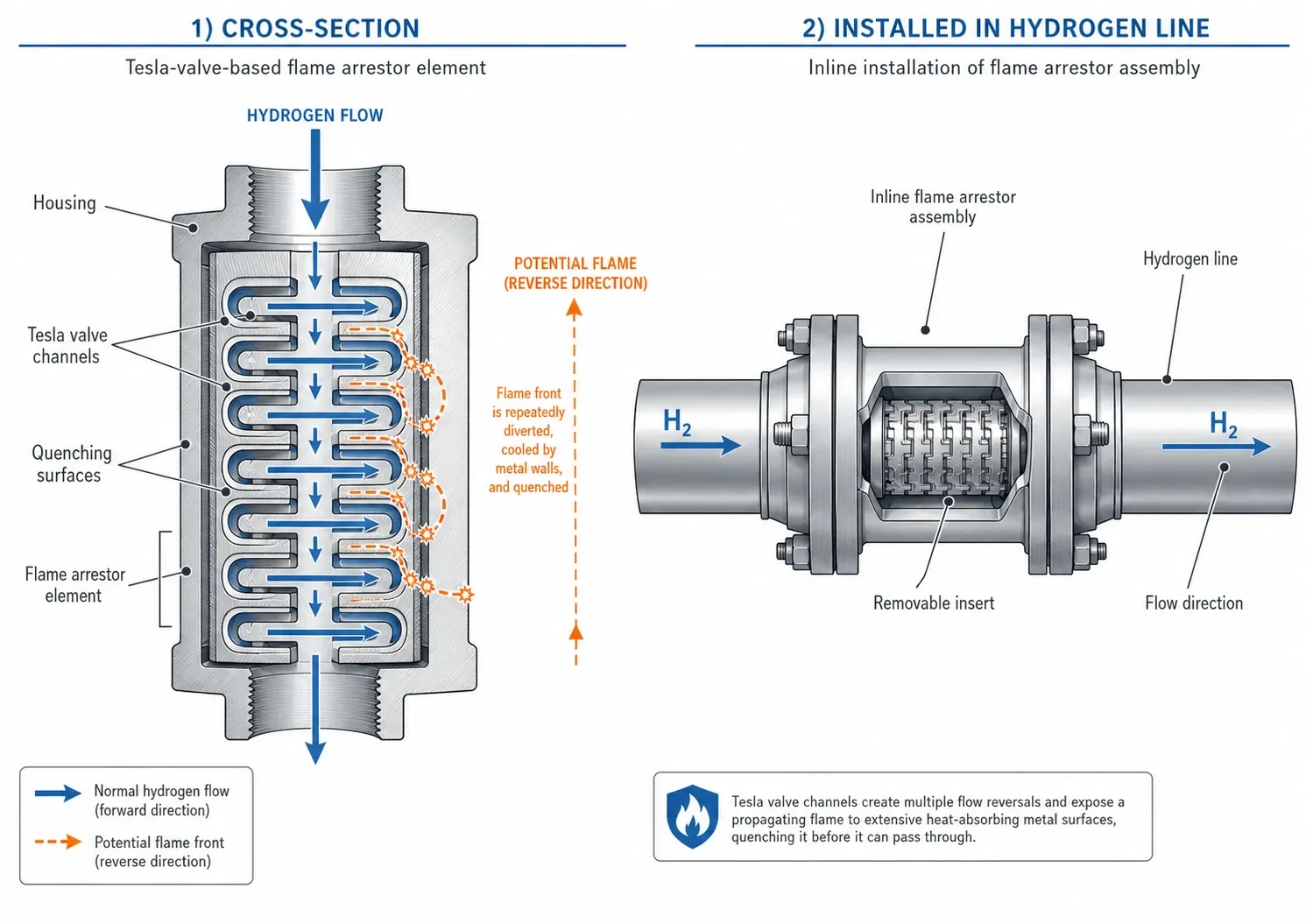
Hydrogen systems pose specific risks of flame flashback and explosion, so flame arrestors and flashback arrestors are critical safety components in many pipelines and devices. Conventional designs often use crimped ribbon elements or finely divided channels to cool and quench the flame front before it can propagate into protected equipment.
Flame quenching and maximum experimental safe gap
Flame arrestor performance is often expressed in terms of the maximum experimental safe gap (MESG), the largest gap between two metal surfaces that still prevents flame propagation for a given gas mixture. Gases with lower MESG values are more prone to propagation through small gaps, so equipment for those gases needs finer elements or different protection strategies.
A recent study on Tesla valve flame arrester units used simulations and experiments to examine how the repeated expansions, contractions and recirculation zones in Tesla valve channels influence flame quenching in hydrogen methane mixtures. For the specific valve geometry and test conditions in that work, Tesla valve structures increased the MESG for methane from 3.0 millimetres to 6.35 millimetres, and for hydrogen from 0.4 millimetres to 0.57 millimetres, relative to straight channels.
In practical terms, this means the studied Tesla valve structure could tolerate a larger effective gap before flashback occurred, which is promising for compact flame arrestor designs that must handle hydrogen rich mixtures. However, these results are specific to one geometry and gas composition set; any Tesla valve based flame arrestor would need full qualification against relevant hydrogen safety standards before use.
Integration into hydrogen piping and devices
Conceptually, Tesla valve segments could be machined or printed into sections of piping or cartridges that act as both flame arrestors and flow rectifiers. Because the Tesla valve geometry inherently adds resistance and turbulence, it will influence both normal operating pressure drop and transient pressure behaviour, which must be captured in system level analysis.
If you are specifying hydrogen equipment, it is essential to treat any Tesla valve based flame arrestor as a safety critical device that must be certified to the same standards as conventional arrestors, not as an informal design tweak. Detailed design should be reviewed by hydrogen and process safety specialists and validated experimentally, particularly for mixtures and operating conditions that differ from published studies.
Design and analysis considerations for engineers
When a Tesla valve is a good fit
Tesla valves are most attractive where you can accept some reverse leakage, where you want to avoid moving parts and where the operating Reynolds number is high enough for inertial effects to be significant. Examples include coolant plates and manifolds in EVs and fuel cells, microfluidic chips with integrated rectification, and flame arrestor units where geometric quenching is the main mechanism.
They are less suitable where you need a very sharp on or off behaviour, minimal forward pressure drop or guaranteed sealing in the reverse direction at low differential pressure. In those cases, conventional check valves or actively controlled valves will usually be simpler and more predictable during design and maintenance.
CFD and optimisation workflows
Because Tesla valve performance is sensitive to geometry, most recent work uses CFD and multi objective optimisation to arrive at useful designs rather than relying on trial and error. Researchers have used open source and commercial CFD codes to study how diodicity varies with stage count, angle, side channel length and channel depth over ranges of Reynolds number from about 50 up to 2000, depending on scale and application.
In the microfluidic regime, parametric studies and topology optimisation have been used to refine geometries for laminar flows, while at larger scales response surface methods and genetic algorithms have been applied to cold plate designs with Tesla valve channel patterns. If your team already uses CFD for manifolds or cold plates, adding a Tesla valve variant to the design space and letting your optimisation pipeline evaluate performance is a practical way to explore the trade offs.
Articles on CFD driven optimisation of flow channels and on AI copilots in mechanical design workflows elsewhere on mechanical-engineering.com are useful companions here, since Tesla valves are a natural candidate for automated geometry tuning.
Prototyping, manufacturing and test
On the manufacturing side, Tesla valves can be machined, cast or additively manufactured into metals and polymers at macro scale, and can be produced in glass or polymers at micro scale using laser machining, lithography and bonding. Ceramic Tesla valves have also been demonstrated using stereolithography; readers interested in a detailed example can refer to the additive manufacturing study “Increasing the diodicity of ceramic Tesla valves by exploiting the design freedom of additive manufacturing”, available via this link.
When you build prototypes, useful measurements include:
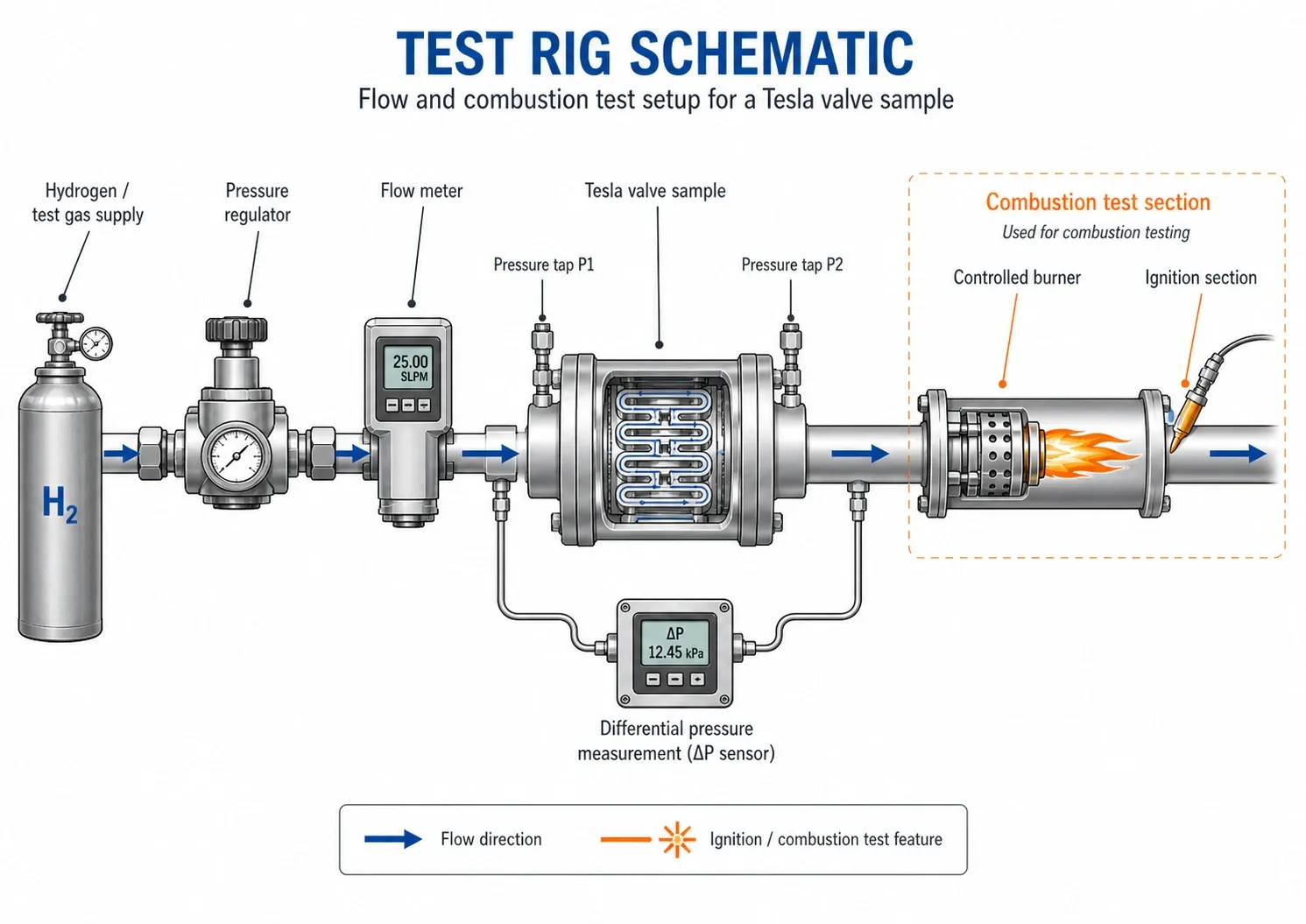
- Pressure drop in both directions as a function of flow rate and derived diodicity.
- Thermal performance such as temperature distribution, maximum temperature and heat transfer coefficient when used in cooling plates.
- Flame propagation and quenching behaviour, including MESG, for hydrogen or other combustible gas applications.
For hydrogen or combustible gas applications, laboratory flame tests and quenching measurements are essential, and any rules of thumb taken from academic work should be treated as starting points only, not design codes.
Practical takeaways for mechanical engineers
Tesla valves give you a way to encode one way bias and mixing directly into geometry, which is appealing in systems where actuators are costly to maintain or difficult to package. The volume of recent peer reviewed work on battery cold plates, power electronics cooling, fuel cells, PV/T systems, microfluidics and hydrogen flame arrestors shows that Tesla valve applications are being taken seriously across multiple domains, even if most examples are still at the simulation or laboratory prototype stage.
If you are a student, a Tesla valve is an excellent case study for CFD, shape optimisation and experimental validation in a lab setting, because the behaviour is rich and easy to visualise. If you are a maintenance professional or technical buyer, it is worth understanding that a Tesla valve based component will behave differently from a conventional check valve and will need appropriate testing and certification in safety critical roles.
For design teams, a low risk way to engage is to treat Tesla valve patterns as candidates in simulation driven design studies for cold plates, manifolds or safety elements, backed by targeted experiments wherever the technology could influence safety or reliability. Any move towards using Tesla valve structures in certified hydrogen safety equipment or in volume production EV coolant manifolds should be supported by detailed testing, standards alignment and expert review of the specific design.


