When creating a part in SolidWorks, that creation is often done empirically and this can lead to a feature manager tree that is littered with suppressed features.
You have the option of re-drawing the part from scratch, but this can be time consuming for complex parts and it also holds the risk of a dimension being incorrectly specified.
The safest thing to do is to clean up the feature tree by removing suppressed features, but this also has a risk attached to it, as sometimes features are dependent on other features.
Below are two methods to make certain that by removing unwanted features, you haven’t changed something that you wanted to keep as it was.
Method 1: Quick and dirty
The first method is really easy, but not completely reliable if some of your features are very small, or prone to a very small difference.
In the first screenshot, two sample parts have been drawn – they deliberately have different features – hole dimensions, depths etc. We’ll use these parts as our samples.
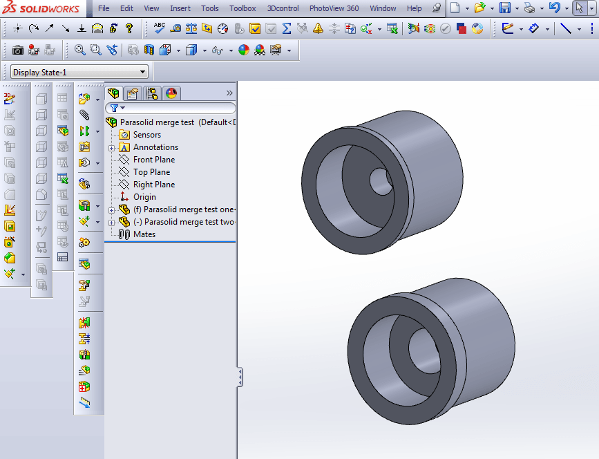
The quickest thing to do is make two copies of your part, colour them differently and mate them in an assembly. Change the transparency of them and where there are any differences, the original colours will remain – in this case, Red and Green.
Method 2: More complex but excellent
The second method is a little more complex, but it will clearly show up even the smallest difference;
Step 1: Save your un-modified part as a Parasolid.
Step 2: Save your modified part as a Parasolid.
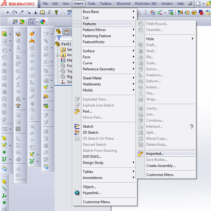
Step 3: Open up a new, blank part file. Insert the unmodified Parasolid part into it by following the steps on the screenshot below.
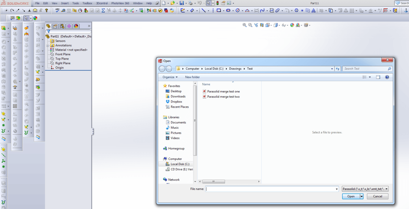
Step 4: This will result in the ‘Open’ window appearing, as below.
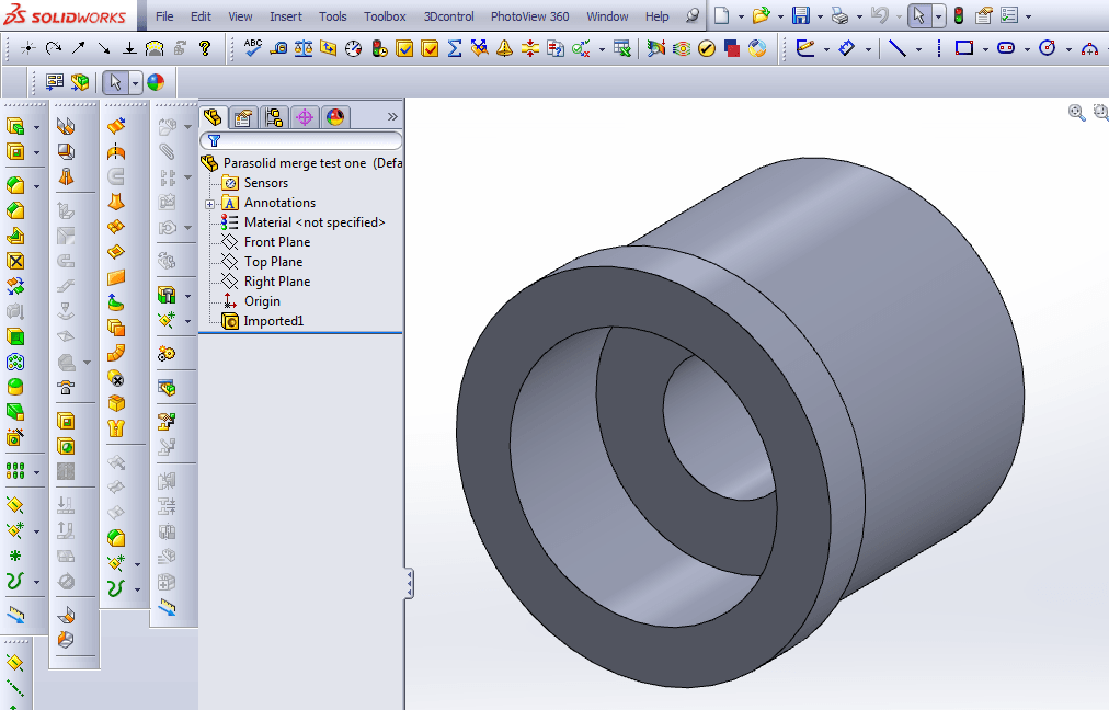
Step 5: You will now see an imported part in your feature tree. In the same part document (do not create a new file), insert your modified Parasolid part by repeating the previous steps.
Step 6: Your parts will now resemble something like the screenshot below. You can see an interfering line in this model.
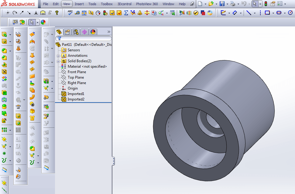
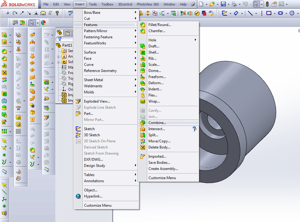
Follow the steps in the screenshot below to combine the two parts.
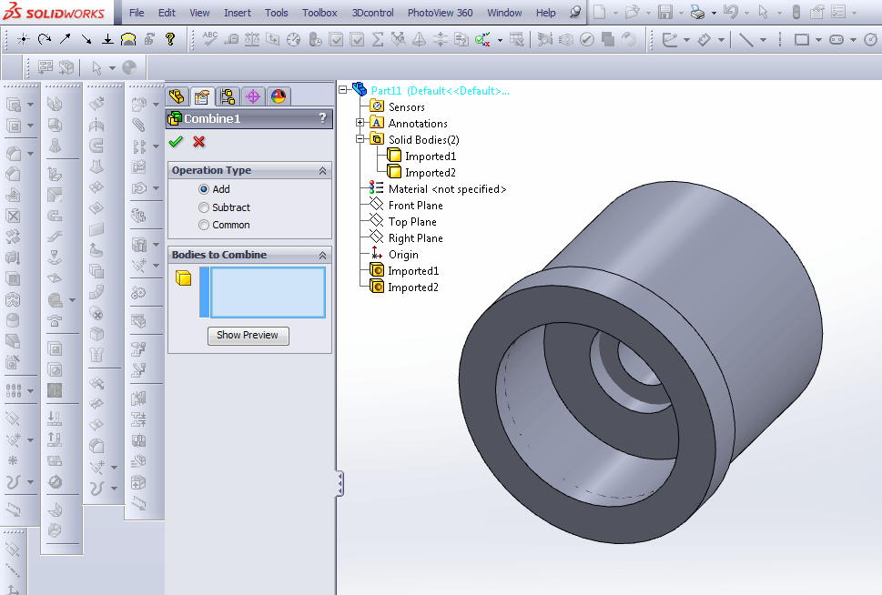
Step 7: You will be asked which bodies you want to combine. Important – select them from the solid bodies feature on the tree, not the imported ones at the bottom.
Note that the ‘Add’ button is checked for operation type.
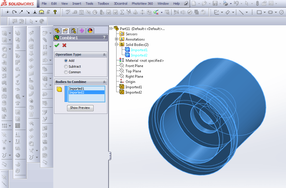
The screenshot below shows which bodies have been selected.
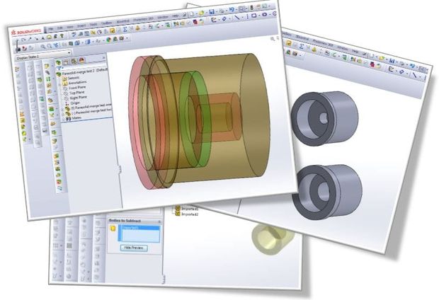
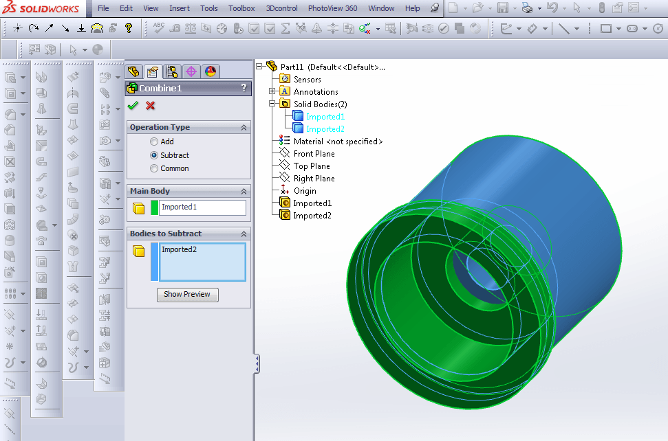
Step 8: Now you are going to subtract one of the bodies – currently, both of them will appear in the selection box – click on either one in the feature tree to select it as the main body. Note that the Subtract button is checked.
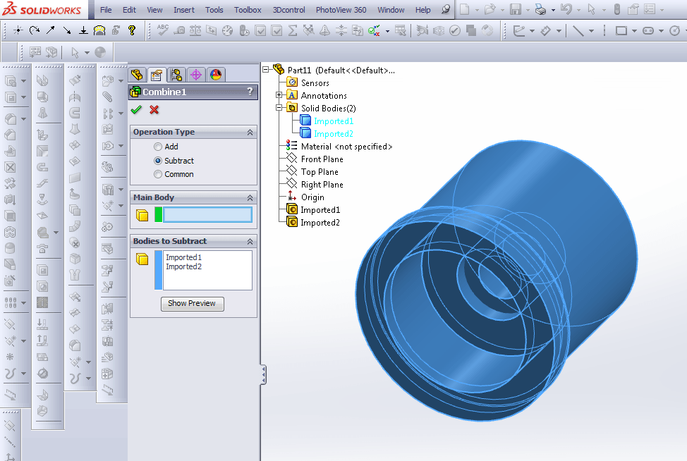
This will result in what is shown below.
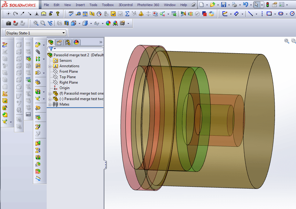
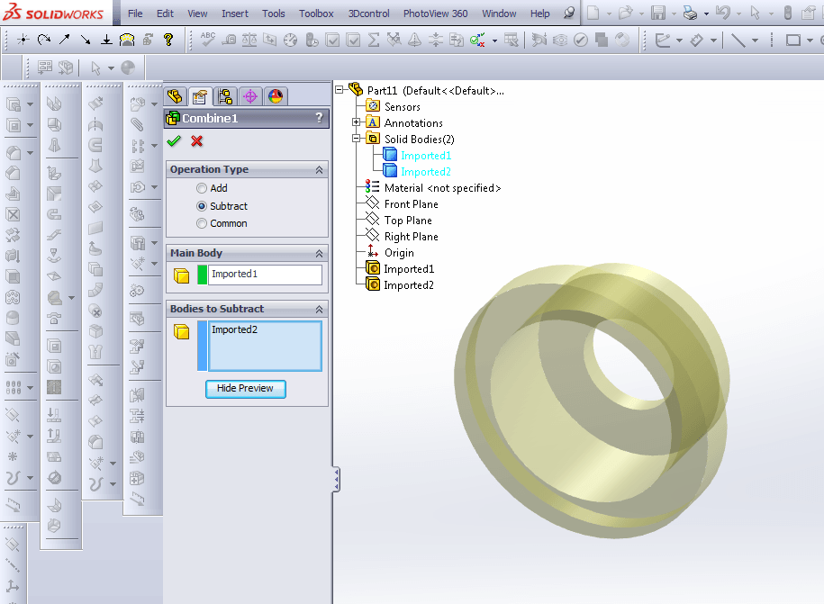
Step 9: Click ‘show preview’. If there is any difference between the modified and unmodified components, they will be revealed to you as below.
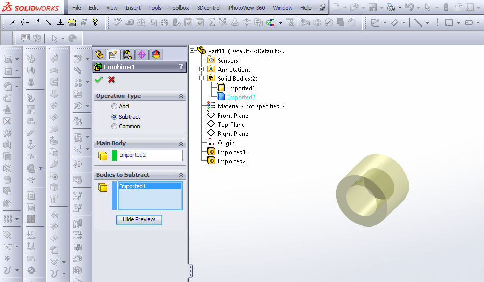
If the main body is changed to the other component, the differences are shown differently.
If your parts are the same, when you click ‘Show preview’, the program will display ‘subtracting will result in empty model’, and this is what you want to see, as your modified part is now identical.